Introduction
Do you need to know how full your oil tank or water tank is, without requiring vast computational effort or expert knowledge? You fill a large barrel with water from the garden hose and would like to cut off the water flow using a magnetic valve when it has reached the desired level? Or maybe you would just like to measure the distance between two objects? The possibilities using the level and range meter described here are virtually limitless! The extent to which cylindrical or cuboid containers are full can be determined either mechanically with a float and potentiometer, or else capacitively with ultrasonics or a laser device. Both approaches, mechanical and capacitive, require auxiliary components such as floats and sensors. If accuracy of measurement is your prime consideration a laser is definitely the best solution, yet even this method has its pitfalls. For example, fog and steam can cause reflections for the laser, falsifying the result. Since influences of this kind affect ultrasonics hardly at all, I settled on ultrasonic sensors for this cost-effective device. A further advantage of this solution is that it requires no physical contact to be made with the liquid medium. Into the bargain we also obtain a tool for measuring distance.
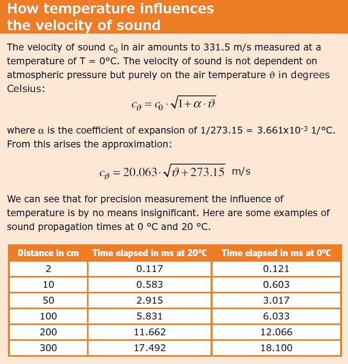
The frequency of 40 kHz normally used by ultrasonic transducers corresponds, at an ambient temperature of 20°C, to a wavelength of 8.5 mm.
Sound waves in this frequency spectrum do not disperse to any great extent and diverge (in a club shaped form) with an aperture angle of around 15°. Perfect qualifications for our purpose then, since the side walls of the container will have effectively no influence on the reflected signal. Accordingly we will keep the functional description short and to the point. A trigger pulse causes the ultrasonic module to transmit a burst signal. This signal is reflected by the object to be measured, say the water surface in a rainwater barrel, and received back by the ultrasonic module as an echo signal. Since the sound traverses the distance to the reflecting object twice during the echo period, we can state that:
distance = 0.5 x velocity of sound [m/s] x echo period [s]
Circuit and Components
The schematic in Figure 1 is based on three components, the well-loved ATmega8 micro-controller, a 4x20 LCD connected to this plus the ultrasonic module. As well as the HC-SR04 module (Figure 2) you can also use the almost identical US-020. Both modules are in the $5/ £3 price class, making them unbeatable attractive for use in a do-it-yourself measurement device.
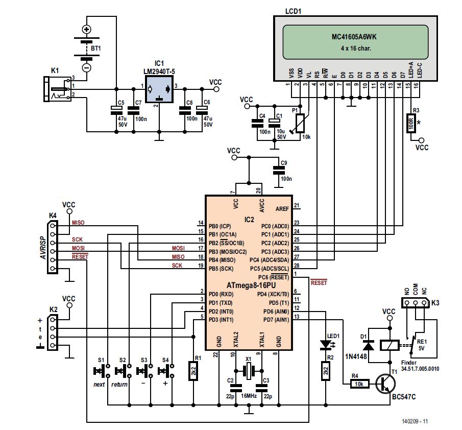
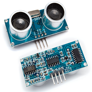
Figure 2.The compact ultrasonic module HC-SR04.
Ascertaining the manufacturers of these modules is not an easy task but they are widely available in electronics stores, particularly those that specialize in robotics. When you check out the data sheets, however, you will discover wide variations. One time the detection distance for the two models will be shown as 2 cm–3 m (.8 inch – 10 feet), another time as 3 cm – 7 m (1.2 inch – 23 feet). Further investigation will uncover other divergent details, even for one and the self-same model. Hence the current consumption will vary between 3mA and 15mA depending on which data sheet you read. Reliable data can be determined only by doing your own research. Generally suppliers of these modules agree on the following data:
- Operating voltage: 5VDC.
- Temperature range: 0–70°C.
- Diffusion angle: 15°.
- Operating frequency: 40kHz.
- Trigger input signal: 10μs.
The minimum distance between transmitter and receiver capsules for the HC-SR04 module is so small that measurements can be made in canisters (the ultrasonic module needs to be discharged when dealing with highly inflammable fluids, owing to risk of explosion!). If you are taking measurements in containers with particularly small aperture diameters you can resort to the SRF02 ([4] ultrasonic module, which although not pin-compatible, is nevertheless equipped with a serial/I2C interface and uses a single capsule for both transmitting and receiving. As the transmit/receive angle is very acute, with this model you need to bear in mind that the minimum distance from the medium being measured amounts to 16cm. To simplify the menu guidance a four-line, 16-character LCD display is employed. Potentiometer P1 adjusts the contrast. R3 is the series resistor for back-illumination and should amount to around
R3 = (5 – Vf) / Inom [Ω].
For this you need to consult the data sheet of the display. With many LCDs the series resistor is already provided internally and in that case you can replace R3 with a wire bridge or strap. To save energy you might also consider a setup involving a switch. The changeover relay RE1, whose contacts are connected to K3, are controlled by port pin PD7 and driver transistor T1, and the alarm LED (low-current) by port pin PD6. A low-dropout voltage regulator LM2940CT-5 ensures a stable 5V supply voltage from four 1.5V batteries. This somewhat exotic voltage regulator delivers up to 1A and can therefore be loaded much more heavily than the usual 78L05 with its 100mA. Naturally you can also use a plug-in (‘wall wart’) AC power supply (<26VDC) for this project, connected to K1. With the relay energized and the LCD illuminated the circuit draws around 150mA. To achieve maximum accuracy of measurement, the microcontroller needs an external 16MHz crystal. A couple of passive components complete the circuitry.
Components List
Resistor:
| R1, R2 = 2.2KΩ | R3 = 0Ω (wire link) | R4 = 10kΩ | P1 = 10kΩ trimpot |
Capacitor:
| C1 = 10μF 50V | C2, C3 = 22pF 50V | C4, C7, C8, C9 = 100μF 50V, 20% | C5, C6 = 47μF 50V |
Semiconductor:
| D1 = 1N4148 | LED1 = Red, 3mm | T1 = BC547C | IC1 = LM2940T-4.0 | IC2 = ATmega8-16PU |
The Control Firmware
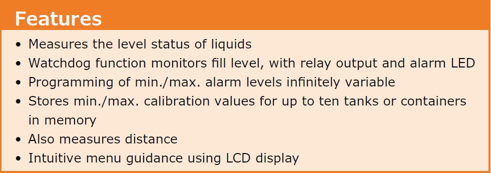
The program in the micro-controller must cover the following functions:
- Indication of the level of liquids.
- Watchdog monitoring of this level with relayoutput and LED alert.
- Infinitely variable programming of the min/max alarm level.
- Storage of min/max calibration values for upto ten containers or tanks.
- Distance measurement.
- Intuitive menu guidance using LCD readout.
- Offset correction for distance measurement.
- Manual divisor correction to accommodate low and high temperature extremes.
The software follows the procedure shown in Figure 3. In view of the limited amount of memory space in the ATmega8, readout messages are given in English only. Operation makes use of the four press buttons Return, Next, Plus and Minus. Because of the complexity of the program coding, which can be downloaded along with the hex file and the PCB layout at [2], it has been subdivided into meaningful procedures and provided with corresponding commentaries, so that even beginners should find their way through it rapidly.
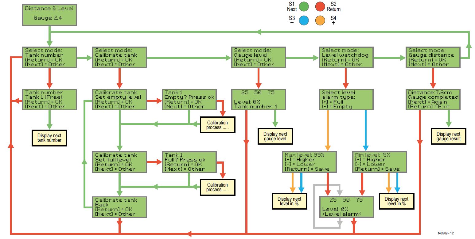
Figure 3.Procedural diagram for the software.
The actual measurement process follows. To bring the ultrasonic module connected to K2 into transmitting a signal, a pulse 10 μs long with a falling edge is sent via port pin PD2 to the trigger input. As a result, about 250μs afterwards, the
ultrasonic module transmits a burst signal with a frequency of 40kHz and duration of 200μs. The echo output, which is connected to the micro-controller via port pin PD3, switches now to High level and the ultrasonic module stands by to receive the reflected signal. If this occurs, the echo output flips back to Low. Timer1 is ticking away throughout this process, so that after the timer is halted, the distance can be calculated. After 50ms if no echo signal arrives, measurement for the current cycle is cancelled. To achieve the best possible results the mensuration cycle involves 16 separate measurements. The program code for this can be examined in the procedure Gauge_distance().
Now a word of advice for people doing their own ‘burning’: you can use Arduino Uno board as controller board for this project. Please refer to " Run with Arduino" tab on how to get running with Arduino Board.

Figure-5

Figure-6

Figure-7

Figure-8

Figure-9

Figure-10
Using Bascom-AVR with Arduino
The ARDUINO is a hardware platform based on AVR processors. ARDUINO boards/chips are programmed with a bootloader. This bootloader is the old STK500 protocol, not longer supported by Atmel in Studio. There are various programmers for ARDUINO, AVRDUDE is probably the most versatile. BASCOM also supports the ARDUINO/STK500 v1 protocol. The DTR/RTS lines are used to reset the board. You can program/read flash/EEPROM but you cannot read/write fuse/lock bytes. The STK500 bootloader for ARDUINO does not support this.
Under options you only need to select the programmer, and the COM port. Since an FTDI chip is used on most ARDUINO boards, this is a virtual COM port. Only present when the USB cable is connected to your PC.
Select 57600baud for the baud rate. Older ARDUINO boards work with 19200baud. Optiboot Bootloader (under Windows 7)
ARDUINO V2:
The developers of the ARDUINO finally implemented the STK500V2 protocol. This protocol is supported by Atmel and of course by BASCOM. Select the ARDUINO STK500V2 programmer in BASCOM programmer options to use this protocol. A board like the MEGA2560 R3 uses this protocol and probably all newer AVR based ARDUINO boards will support this protocol. The baud rate should be 115200 but could be different for your board.
Using Bascom-AVR with Arduino Optiboot Bootloader (under Windows 7):
For more information on Optiboot visit following website: http://code.google.com/p/optiboot/
- Download AVRDUDE from http://www.nongnu.org/avrdude/
- Latest Windows Version (April 2012): avrdude-5.11-Patch7610-win32.zip. Complete link:
- Create a folder like c:AVRDUDE
- Copy the content of avrdude-5.11-Patch7610-win32.zip in this new folder
- Open Bascom-AVR
- Click on Options >>> Programmer
- Choose External programmer
- Checkmark Use HEX file
- Include the path to avrdude.exe
- User Parameter: -C c:avrdudeavrdude.conf -p m328p -P com19 -c arduino -b 115200 -U flash:w:{FILE}:i

Explanation of Parameter:
-C
c:avrdudeavrdude.conf The config file tells avrdude about all the different ways it can talk to the programmer.
-p
m328p This is just to tell it what microcontroller its programming. For example, if you are programming an Atmega328p, use m328p as the partnumber
-P
com19 This is the communication port to use to talk to the programmer (COM19) in this case. Change it to your COM port.
-c
arduino
Here is where we specify the programmer type, if you're using an STK500 use stk500, use arduino for Optiboot
-b
115200
Set serial baudrate for programmer. Use 115200 baud for Optiboot.
-U
flash:w:{FILE}:i
You define here:
- the memory type: flash or eeprom (this could be also hfuse, lfuse or effuse if you want to verfiy this)
- r (read), w (write) or v (verify)
- Use {FILE} to insert the filename {EEPROM} to insert the filename of the generated EEP file.
- i = Intel Hex File
After clicking on the F4 (Program Chip) Button in Bascom-AVR you see the CMD window of Windows 7 until AVRDUDE is ready flashing the Arduino.

Complete documentation of AVRDUDE parameters
http://avrhelp.mcselec.com/index.html?arduino.htm