Chapter – 3: Interfacing with Liquid Crystal Display
In this chapter, you learn how to connect an LCD to your Arduino, and you learn how to use the Arduino LiquidCrystal library to write text and arbitrary custom characters to your LCD. After you have the basics down, you add some components to make a simple thermostat capable of obtaining local temperature data, reporting it to you, and controlling a fan to compensate for heat. An LCD will give you live information, a speaker will alert you when the temperature is getting too hot, and the fan will turn on to automatically cool you down.
 Figure 3-1: LCD with Headers soldered on
Parts Needed for this Tutorial
Setting Up the LCD
To complete the examples in this chapter, we use a parallel LCD screen. These are extremely common and come in all kinds of shapes and sizes. The most common is a 16×2 character display with a single row of 16 pins (14 if it does not have a backlight). In this chapter, we use a 16-pin LCD display that can show a total of 32 characters (16 columns and 2 rows).
If your display didn’t come with a 16-pin header already soldered on, you need to solder one on so that you can easily install it in your breadboard. With the header successfully soldered on, your LCD should look like the one shown in Figure 3-1, and you can insert it into your breadboard.
Next, you wire up your LCD to a breadboard and to your Arduino. All of these parallel LCD modules have the same pin-out and can be wired in one of two modes: 4-pin or 8-pin mode. You can accomplish everything you might want to do using just 4 pins for communication; that’s how you’ll wire it up. There are also pins for enabling the display, setting the display to command mode or character mode, and for setting it to read/write mode. Table 3-1 describes all of these pins.
| PIN NUMBER | PIN NAME | PIN PURPOSE |
| 1 | VSS | Ground connection |
| 2 | VDD | +5V connection power supply |
| 3 | VO | Contrast adjustment (to potentiometer) |
| 4 | RS | Register selection (Character vs. Command) |
| 5 | RW | Read/write |
| 6 | EN | Enable |
| 7 | D0 | Data line 0 |
| 8 | D1 | Data line 1 |
| 9 | D2 | Data line 2 |
| 10 | D3 | Data line 3 |
| 11 | D4 | Data line 4 |
| 12 | D5 | Data line 5 |
| 13 | D6 | Data line 6 |
| 14 | D7 | Data line 7 |
| 15 | A | Backlight anode |
| 16 | K | Backlight cathode |
Table 3-1: Parallel LCD Pins assignment
Here’s a breakdown of the pin connections:
- The contrast adjustment pin changes how dark the display is. It connects to the center pin of a potentiometer.
- The register selection pin sets the LCD to command or character mode, so it knows how to interpret the next set of data that is transmitted via the data lines. Based on the state of this pin, data sent to the LCD is either interpreted as a command (for example, move the cursor) or characters (for example, the letter a).
- The RW pin is always tied to ground in this implementation, meaning that you are only writing to the display and never reading from it.
- The EN pin is used to tell the LCD when data is ready.
- Data pins 4~7 are used for actually transmitting data, and data pins 0~3 are left unconnected.
- You can illuminate the backlight by connecting the anode pin to 5V and the cathode pin to ground if you are using an LCD with a built-in resistor for the backlight. If you are not, you must put a current-limiting resistor in-line with the anode or cathode pin. The datasheet for your device will generally tell you if you need to do this.
We can connect the communication pins of the LCD to any I/O pins on the Arduino. In this chapter, they are connected as shown in Table 3-2.
| LCD PIN | ARDUINO Uno PIN NUMBER |
| RS | Pin 2 |
| EN | Pin 3 |
| D4 | Pin 4 |
| D5 | Pin 5 |
| D6 | Pin 6 |
| D7 | Pin 7 |
Table 3-2: Communication Pins Connections
Reference the wiring diagram shown in Figure 3-2 and hook up your LCD accordingly.
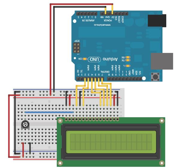 Figure 3-2: LCD wired to breadboard and Arduino
Now your LCD is ready for action! Once you get the code loaded in the next section, you can start displaying text on the screen. The potentiometer will adjust the contrast between the text and the background color of the screen.
Using the LiquidCrystal Library to Write to the LCD
The Arduino IDE includes the LiquidCrystal library, a set of functions that makes it very easy to interface with the parallel LCD that you are using. The LiquidCrystal library has an impressive amount of functionality, including blinking the cursor, automatically scrolling text, creating custom characters, and changing the direction of text printing. This chapter does not cover every function, but instead gives you the tools you need to understand to interface with the display using the most important functions. You can find descriptions of the library functions and examples illustrating their use on the Arduino website:
http://arduino.cc/en/Reference/LiquidCrystal
Adding Text to the Display
In this first example, we add some text and an incrementing number to the display. This exercise demonstrates how to initialize the display, how to write text, and how to move the cursor. First, include the LiquidCrystal library:
#include <LiquidCrystal.h>
Then, initialize an LCD object, as follows:
LiquidCrystal lcd (2, 3, 4, 5, 6, 7);
The arguments for the LCD initialization represent the Arduino pins connected to RS, EN, D4, D5, D6, and D7, in that order. In the setup, you call the library’s begin() function to set up the LCD display with the character size.
(The one we are using is a 16×2 display, but you might be using another size, such as a 20×4). The arguments for this command represent the number of columns and the number of rows, respectively:
lcd.begin(16, 2);
After doing that, you can call the library’s print() and setCursor() commands to print text to a given location on the display. For example, if you want to print your name on the second line, you issue these commands:
lcd.setCursor(0, 1);
lcd.print(“Mr. Arduino Uno”);
The positions on the screen are indexed starting with (0,0) in the top-left position. The first argument of setCursor() specifies which column number, and the second specifies which row number. By default, the starting location is (0,0). So, if you call print() without first changing the cursor location, the text
starts in the top-left corner.
WARNING: The library does not check for strings that are too long. So, if you try to print a string starting at position 0 that is longer than the number of characters in the row you are addressing, you might notice strange behavior. Make sure to check that whatever you are printing will fit on the display!
Using this knowledge, we can now write a simple program that displays some text on the first row and that prints a counter that increments once every second on the second row. Listing 3-1 shows the complete program to accomplish this. Load it on to your Arduino and confirm that it works as expected. If you don’t see anything, adjust the contrast with the potentiometer.
Listing 3-1: LCD Text with an Incrementing Number—LCD_text.ino
/*
This program is free software: you can redistribute it and/or modify
it under the terms of the GNU General Public License v3 as published by
the Free Software Foundation.
*/

//LCD text with incrementing number

//Include the library code:
#include <LiquidCrystal.h>

//Start the time at 0
int time = 0;

//Initialize the library with the numbers of the interface pins
LiquidCrystal lcd(2, 3, 4, 5, 6, 7);

void setup()
{
  //Set up the LCD's number of columns and rows:
  lcd.begin(16, 2);
  // Print a message to the LCD.
  lcd.print("Mr. Arduino Uno");
}

void loop()
{
  //Move cursor to second line, first position
  lcd.setCursor(0,1);
  //Print Current Time
  lcd.print(time);
  //Wait 1 second
  delay(1000);
  //Increment the time
  time++;
}
This program combines all the steps that you learned about earlier. The library is first included at the top of the program. A time variable is initialized to 0, so that it can be incremented once per second during the loop(). A LiquidCrysal object called lcd is created with the proper pins assigned based on the circuit we’ve already wired up. In the setup, the LCD is configured as having 16 columns and 2 rows, by calling lcd.begin(16,2). Because the first line never changes, it can be written in the setup. This is accomplished with a call to lcd.print(). Note that the cursor position does not need to be set first, because we want the text to be printed to position (0,0), which is already the default starting location. In the loop, the cursor is always set back to position (0,1) so that the number we print every second overwrites the previous number. The display updates once per second with the incremented time value.
Creating Special Characters and Animations
What if we want to display information that cannot be expressed using normal text? Maybe we want to add a Greek letter, a degree sign, or some progress bars. Thankfully, the LiquidCrystal library supports the definition of custom characters that can be written to the display. In the next example, we use this capability to make an animated progress bar that scrolls across the display. After that, we take advantage of custom characters to add a degree sign when measuring and displaying temperature.
Creating a custom character is pretty straightforward. If we take a close look at the LCD, you’ll see that each character block is actually made up of a 5×8 grid of pixels. To create a custom character, we simply have to define the value of each of these pixels and send that information to the display. To try this out, we make a series of characters that will fill the second row of the display with an animated progress bar. Because each character space is 5 pixels wide, there will be a total of five custom characters: one with one column filled, one with two columns filled, and so on.
At the top of our sketch where we want to use the custom characters, create a byte array with 1s representing pixels that will be turned on and with 0s representing pixels that will be turned off. The byte array representing the character that fills the first column (or the first 20% of the character) looks like this:
byte p20[8] = {
B10000,
B10000,
B10000,
B10000,
B10000,
B10000,
B10000,
B10000,
};
We chose to call this byte array p20, to represent that it is filling 20 percent of one character block (the p stands for percent). In the setup() function, call the createChar() function to assign our byte array to a custom character ID. Custom character IDs start at 0 and go up to 7, sowe can have a total of eight custom characters. To map the 20% character byte array to custom character 0, type the following within our setup() function:
lcd.createChar(0, p20);
When we’re ready to write a custom character to the display, place the cursor in the right location and use the library’s write() function with the ID number:
lcd.write((byte)0);
In the preceding line, (byte) casts, or changes, the 0 to a byte value. This is necessary only when writing character ID 0 directly (without a variable that is defined to 0), to prevent the Arduino compiler from throwing an error caused by the variable type being ambiguous. Try removing the “byte cast” and observe the error that the Arduino IDE displays. We can write other character IDs without it, like this:
lcd.write(1);
Putting this all together, we can add the rest of the characters and put two nested for() loops in our program loop to handle updating the progress bar.
The completed code looks like the code shown in Listing 3-2.
Listing 3-2: LCD Updating Progress Bar Code—LCD_progress_bar.ino
/*
This program is free software: you can redistribute it and/or modify
it under the terms of the GNU General Public License v3 as published by
the Free Software Foundation.
*/

//LCD with Progress Bar

//Include the library code:
#include <LiquidCrystal.h>

//Initialize the library with the numbers of the interface pins
LiquidCrystal lcd(2, 3, 4, 5, 6, 7);

//Create the progress bar characters
byte p20[8] = {
  B10000,
  B10000,
  B10000,
  B10000,
  B10000,
  B10000,
  B10000,
  B10000,
};
byte p40[8] = {
  B11000,
  B11000,
  B11000,
  B11000,
  B11000,
  B11000,
  B11000,
  B11000,
};
byte p60[8] = {
  B11100,
  B11100,
  B11100,
  B11100,
  B11100,
  B11100,
  B11100,
  B11100,
};
byte p80[8] = {
  B11110,
  B11110,
  B11110,
  B11110,
  B11110,
  B11110,
  B11110,
  B11110,
};
byte p100[8] = {
  B11111,
  B11111,
  B11111,
  B11111,
  B11111,
  B11111,
  B11111,
  B11111,
};

void setup()
{
  //Set up the LCDs number of columns and rows:
  lcd.begin(16, 2);
  // Print a message to the LCD.
  lcd.print("Jeremy's Display");

  //Make progress characters
  lcd.createChar(0, p20);
  lcd.createChar(1, p40);
  lcd.createChar(2, p60);
  lcd.createChar(3, p80);
  lcd.createChar(4, p100);
}

void loop()
{
  //Move cursor to second line
  lcd.setCursor(0,1);
  //Clear the line each time it reaches the end
  //with 16 " " (spaces)
  lcd.print("                ");

  //Iterate through each character on the second line
  for (int i = 0; i<16; i++)
  {
    //Iterate through each progress value for each character
    for (int j=0; j<5; j++)
    {
      lcd.setCursor(i, 1); //Move the cursor to this location
      lcd.write(j);        //update progress bar
      delay(100);          //wait
    }
  }
}
At the beginning of each pass through the loop, the 16-character-long string of spaces is written to the display, clearing the progress bar before it starts again. The outer for() loop iterates through all 16 positions. At each character position, the inner for() loop keeps the cursor there and writes an incrementing progress bar custom character to that location. The byte cast is not required here because the ID 0 is defined by the j variable in the for() loop.