Chapter -2: Digital input and output
This chapter covers:
- Blinking more than one LED
- Using a push button to control a sequence of blinking LEDs
- Building a project step by step
- Learning about interrupts
- Building a reactometer
Now that you have a sense of what an Arduino can do and have completed your first test run, it’s time to delve deeper. You’re going to build on what you learned in chapter 1 and build your first complete project, a reactometer that uses LEDs, a push button, and a timer to record reaction times. Let’s get started…
2.1 Getting started
To complete your reactometer, you need a handful of components:
- A breadboard on which to assemble the project
- A selection of jumpers to connect components together
- Six red LEDs; you can use other colors if you want
- One green LED
- One momentary-contact push button
- Seven resistors, each around 180 ohms or slightly greater in value
- One 10k ohm resistor
You can see these components in figure 2.1. Next, you’ll assemble the circuit on a breadboard.
 Figure 2.1 The components required to complete this tutorial
2.1.1 Using a breadboard
Breadboards are great for assembling circuits, particularly during the development phase of a project, because they make it easy to move components around or add new ones. A typical breadboard layout is shown in figure 2.2. The breadboard is made up of a number of sockets. In the central part of the board, the sockets are connected vertically with a break in the center, and they’re connected horizontally at the top and bottom. The top and bottom areas are used to provide the power supplies to the circuit being built. Connections between components are made using jumpers of varying lengths. It’s now time to start populating the breadboard by adding your first batch of LEDs and resistors.
2.1.2 Circuit diagram
For the first part of the project, you’re going to add five LEDs to the breadboard. Figure 2.3 shows a diagram, or schematic, of the circuit you’re going to build. Don’t worry if you don’t understand it at the moment—you’ll soon get the hang of reading a circuit diagram and translating it to use on a breadboard. In the circuit diagram, digital pins D8 to D12 of the Arduino each connect to an LED (LED1 through LED5); a current-limiting resistor is connected to each LED (R1 through R5). The cathode, normally the shorter leg of each LED, is connected to GND on the Arduino. Power for the circuit is provided by the USB connection to your computer. When you’ve made yourself familiar with the circuit diagram and have seen how the LEDs, resistors, and Arduino connect together, you can move onto placing the components into the breadboard.
 Figure 2.2 Breadboard layout: the sockets in the top and bottom two rows are connected horizontally; the other sockets are connected vertically with a break in the center of the breadboard.
 Figure 2.3 Schematic diagram showing Arduino connected to five LEDs
2.1.3 Adding the LEDs
In figure 2.3, LED1 through LED5 are connected to digital pins 8 through 12 on the Arduino, which are labeled D8 through D12 on the schematic diagram. Each LED goes to a separate pin. A resistor is connected in series with each LED; these are current-limiting resistors, and they act to limit the amount of current that flows through the LEDs, protecting them from burning out.
2.1.4 Connecting the hardware
Make sure the Arduino isn’t connected to your computer yet; you don’t want to have it powered up while you’re connecting the hardware. Figure 2.4 shows how to make the first connection to the first LED by connecting a jumper from pin 12 on the Arduino to the first resistor.
 Figure 2.4 Making connections to the first LED with a current limiting resistor and pin 12 of the Arduino
Note that the resistor jumps over the break in the breadboard; make sure that the longer leg, or anode, of the LED connects to the resistor, and the shorter leg, or cathode, to GND on the top power rail. Now connect the other four LEDs as shown in figure 2.5, following the same pattern as for the first LED.
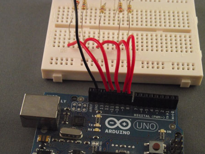 Figure 2.5 Connections of the five resistors to pins 8 through 12 on the Arduino
Figure 2.6 shows the completed circuit. Note the connection of the long jumper from GND on the Arduino to the common rail on the breadboard. You can use the USB connection to provide the power for this project because the LEDs only require a small amount of current. Now that you’ve finished assembling the circuit, you can move on to develop your code sketch to make the LEDs flash.
 Figure 2.6 The completed circuit with power being provided by the USB connection
2.1.5 Sketch to flash five LEDs
With the connection of the hardware complete, you can now start to program your code sketch. Launch the Arduino IDE and start a new sketch. Carefully type the following code into the editor window.
int ledArray[] = {8, 9, 10, 11, 12};
int count = 0;
int timer = 75;
void setup(){
for (count=0;count<5;count++){
pinMode(ledArray[count], OUTPUT);
}
}

void loop(){
for (count=0;count<5;count++){
digitalWrite(ledArray[count], HIGH);
delay(timer);
digitalWrite(ledArray[count], LOW);
delay(timer);
}
}
Listing 2.1 Five flashing LEDs, flashing after each other
In the first part of the sketch, the sketch variables are declared. An array, ledArray, is used to set the digital pin numbers you’re going to use. You could have used direct pin assignment, as shown here:
int ledPin1 = 8;
int ledPin2 = 9;
int ledPin3 = 10;
int ledPin4 = 11;
int ledPin5 = 12;
But it’s more efficient to use an array when you have a collection of pin numbers that you’ll treat similarly. During the setup routine, you use a for loop so that each pin from 8 through 12 is set as an output.
In the sketch’s main loop, you use another for loop to set each pin in turn to HIGH, turning the LED on with a digitalWrite function that accesses the LED to be written to from the ledArray array by its index value, count. Then, after a delay of 75 milliseconds, the pin is set to LOW and the LED is turned off again using digitalWrite. The loop continues to run, turning each LED on and off in turn, with a slight delay in between. You could alter the delay time by changing the value of the timer variable.
NOTE: The digitalWrite function works by writing either a HIGH or a LOW value to the pin. If the pin is set to HIGH, digitalWrite sets the pin at 5V, which is enough to power an LED; if the pin is set to LOW, digitalWrite sets the pin at 0V, which turns the LED off.
Now that you’ve built your circuit and written your sketch, let’s move on and test it.
2.1.6 Upload and test
Connect the USB cable between your computer and the Arduino and then verify that the sketch will compile. If any errors are generated, check that you’ve typed the code exactly as shown in listing 2.1. Pay careful attention to opening and closing braces, {}, and to the semicolons (;). Once the sketch compiles correctly, upload it to the Arduino. If you see any error messages, check that the correct Arduino type and serial port have been selected.
Once the sketch has been uploaded to the Arduino, and after a short delay, the LEDs should start to flash in turn. If no errors are generated and the sketch uploads correctly to the Arduino, but the LEDs don’t flash, disconnect the Arduino from the USB cable and carefully check your connections. Check that the LEDs are plugged in correctly, with the cathodes connected to ground, and then try connecting the USB cable again.
NOTE You shouldn’t need to re-upload the sketch because the Arduino should retain the code in its onboard memory.
Your LEDs are now flashing, so it’s time to make things more complex. In the next part of the tutorial, you’re going to add a push button to the circuit.
2.2 Gaining control
Now that your sketch is working, with the LEDs flashing on and off in turn, it’s time to add some control to the circuit by adding a push button. This will be used to start and stop the LEDs’ flashing sequence.
2.2.1 Circuit diagram
The circuit diagram is shown in figure 2.7. You’ll keep the same components that you used for the first version and add a push button (S1) and a resistor (R6) with a value of 10k ohms. Once you’ve had a chance to study the updated circuit diagram, you can add the new components to the breadboard.
 Figure 2.7 Schematic of an Arduino connected to five LEDs controlled by a push button
2.2.2 Connections
First, disconnect the Arduino from the USB cable, and then mount the push button onto the breadboard, as shown in figure 2.8. Note how it straddles the center of the breadboard. The resistor R6 is used as a pull-down resistor, which prevents the input to D2 from floating and ties the input D2 to ground (GND), LOW, when the switch isn’t being pressed. When the switch is pressed, the input to D2 switches to 5V or HIGH. Figure 2.9 shows an overview of the completed circuit laid out on the breadboard; the Arduino’s power is provided by the USB cable connected to the computer.
 Figure 2.8 Connecting the push button to the breadboard
Once you’ve connected the push button and additional resistor, it’s time to look at the code side of things. In this sketch, you’re going to use a special feature of the Arduino called an interrupt.
2.2.3 Interrupts butting in
Interrupts on the Arduino are very powerful; they can interrupt the sketch or program flow at any time. An interrupt is like someone ringing the doorbell when you’re just about to step into the shower—you have to deal with it immediately. The Arduino is exactly the same; when an interrupt is signaled, your sketch must go and deal with it. The standard Arduino can use a maximum of two interrupts, but for this project you’re going to use just one. The interrupt will detect when the push button has been pressed; pressing the push button the first time stops the lighting up sequence of the LEDs, pressing it again restarts the sequence, and so on.
 Figure 2.9 The completed circuit connected to the USB for power
2.2.4 Sketch to control the LEDs with a push button
The following listing shows the new sketch. You can either amend your existing sketch or start a new one.
/* leds 5 in a row start stop with an interrupt
 *
 */

volatile int state = LOW;
int ledArray[] = {8, 9, 10, 11, 12};
int count = 0;
int timer = 75;
int pause = 500;

void setup(){
  for (count=0;count<5;count++){
    pinMode(ledArray[count], OUTPUT);
  }
  attachInterrupt(0, ledOnOff, RISING);
}

void loop(){
  if (state) {
    for (count=0;count<5;count++){
      digitalWrite(ledArray[count], HIGH);
      delay(timer);
    }
    delay(pause);

    for (count=0;count<5;count++){
      digitalWrite(ledArray[count], LOW);
      delay(timer);
    }
    delay(pause);
  }
}

void ledOnOff() {
  static unsigned long lastMillis = 0;
  unsigned long newMillis = millis();
  if (newMillis - lastMillis < 50){
  }
  else {
    state = !state;
    lastMillis = newMillis;
  }
}
Listing 2.2 Start-stop display
At the beginning of this code, you declare the state variable as volatile. The volatile keyword is used for variables that can be altered by something outside the part of the sketch where it appears; one of the main uses of volatile is when using interrupts, as we’re doing here.
The standard Arduino has two interrupts: interrupt 0 is attached to digital pin 2, and interrupt 1 is attached to digital pin 3. The Arduino Mega has an additional four interrupts: interrupt 2 is attached to digital pin 21, interrupt 3 is attached to digital pin 20, interrupt 4 is attached to digital pin 19, and interrupt 5 is attached to digital pin 18.
NOTE: The function attachInterrupt(interrupt, function, mode) takes three arguments. The first is interrupt, which can be set to 0 or 1; the second is the function to call, which must have no arguments and return nothing; and the third is the mode that generates the interrupt. This mode can have one of four values: LOW triggers whenever the pin is low; CHANGE triggers whenever the pin changes value; RISING triggers whenever the pin changes from LOW to HIGH; and FALLING triggers whenever the pin changes from HIGH to LOW.
In this sketch, you set the interrupt to RISING. The interrupt will be triggered when the push button is pressed and the pin switches from LOW to HIGH. Another change in this sketch is that now the LEDs light up one after the other with a slight delay between each; then, when all the LEDs are lit, there is a slight pause and all the LEDs are switched off. The sequence then repeats. Pressing the push button stops the sequence; pressing it again restarts it.
In this sketch, you counter the effect of the switch bouncing by using a static variable called lastMillis. Static variables keep their values between calls to a function. The millis() function returns the number of milliseconds since the program started, and each time the interrupt-service routine is called, you assign the value of millis() to the variable newMillis. You then compare the value of newMillis to lastMillis; if the result is less than 50 milliseconds (the bounce period), you do nothing and return to the main sketch loop. If the value is greater than or equal to 50 milliseconds, you’re outside the bounce period, meaning that the button has really been pressed again. In that case, you update the state variable and assign the value of newMillis to lastMillis before returning to the main sketch loop.
CAUTION: Many people consider interrupts an advanced technique, but if you’re careful, you should have no problem using them. During interrupt service routines, keep your sketch code as small as possible; this will help you avoid unexpected things happening in the rest of your sketch. Another caveat is that you can’t use the delay function inside an interrupt-service routine.
Let’s move on now and test our newest sketch.
2.2.5 Upload and test
Connect the Arduino to your computer with the USB cable. Verify that the sketch compiles correctly, and then upload it to the Arduino. When the sketch has completed uploading, no LEDs will be lit until you press the push button. Try pressing the push button a few times to see how the LED sequence starts and stops.
2.2.6 Time for a break
Keeping the same circuit, you’re now going to add a statement called a break to your sketch; the break command is used to break out of a loop or switch statement. You’re going to use it stop the LED sequence and leave the LED lights lit until the button is pressed again, so if three LEDs are lit when the button is pressed, three will stay lit until the button is pressed again and the sequence starts over. The following listing shows the new sketch with the break command.
Listing 2.3: Adding a break
volatile int state = LOW;
int ledArray[] = {8, 9, 10, 11, 12};
int count = 0;
int timer = 75;
int pause = 500;
void setup()
{
for (count=0;count<5;count++)
{
pinMode(ledArray[count], OUTPUT);
}
attachInterrupt(0, ledOnOff, RISING);
}
void loop()
{
if (state)
{
for (count=0;count<5;count++){
digitalWrite(ledArray[count], HIGH);
delay(timer);
if (!state) {break;}
}
delay(pause);
if (state)
{
for (count=0;count<5;count++)
{
digitalWrite(ledArray[count], LOW);
}
delay(pause);
}
}
}
void ledOnOff()
{
static unsigned long lastMillis = 0;
unsigned long newMillis = millis();
if (newMillis – lastMillis < 50){ }
else
{
state = !state;
lastMillis = newMillis;
}
}
After each LED lights up, you check the status of the state variable to see if the push button has been pressed. If the button has been pressed, the break statement is called and the sketch exits from the loop. When the button is pressed again, the sequence restarts. It’s now time to check that your sketch functions correctly.
2.2.7 Upload and test
Verify that the sketch compiles correctly, and then upload and test it. When the button is pressed the sequence of flashing LEDs should halt; pressing it again should restart the sequence. It’s now time to move on to the next stage of your project. You’re going to make a reaction tester.
2.3 Reaction tester
This is the last circuit change you’re going to make in this chapter. You’re going to add two LEDs to the circuit, preferably a green one and a red one, to be used as start and stop indicators. The red LED will initially be lit; when it goes out and the green LED lights up, you’ll have to press the push button as quickly as you can to halt the light sequence you set up in the previous section. Someone with an average reaction time should be able to stop the sequence when two or three LEDs are lit.
2.3.1 Circuit diagram
Look at the circuit diagram in figure 2.10 and note how the two new LEDs connect to the Arduino. Green LED6 and red LED7 have been added to the circuit, along with two 220Ω current-limiting resistors, R7 and R8.
2.3.2 Connections
Figure 2.11 shows the completed connections between the Arduino and breadboard, with the two additional LEDs and resistors added to the existing circuit. That’s the circuit completed for this chapter. It’s now time to look at your penultimate sketch for this chapter.
 Figure 2.10 Schematic of Arduino with a push button and seven LEDs: two of them are used as start/stop indicators.
2.3.3 Sketch to test reaction speed
The next listing shows the sketch for the reaction meter; type it carefully into a new sketch.
Listing 2.4 Reaction tester
volatile int state = 0;
int ledArray[] = {8, 9, 10, 11, 12};
int count = 0;
int timer = 50;
int stopLed = 6;
int goLed = 7;
int randMin = 250;
int randMax = 750;
int startDelay;
void setup()
{
for (count=0;count<5;count++)
{
pinMode(ledArray[count], OUTPUT);
}
attachInterrupt(0, ledOnOff, RISING);
pinMode(stopLed, OUTPUT);
pinMode(goLed, OUTPUT);
randomSeed(analogRead(0));
}
void loop()
{
//start state
if (state == 0) {
digitalWrite(stopLed, HIGH);
digitalWrite(goLed, LOW);
for (count=0;count<5;count++){
digitalWrite(ledArray[count], LOW);
}
}
// start button pressed
if (state == 1) {
// random start
startDelay = random(randMin,randMax);
delay(startDelay);
digitalWrite(stopLed, LOW);
digitalWrite(goLed, HIGH);
for (count=0;count<5;count++){
digitalWrite(ledArray[count], HIGH);
delay(timer);
if (state == 2) {
break;
}
}
}
}
void ledOnOff()
{
static unsigned long lastMillis = 0;
unsigned long newMillis = millis();
if (newMillis – lastMillis < 50){
}
else {
state = state++;
if (state == 3) {
state = 0;
}
lastMillis = newMillis;
}
}
In this sketch, you set the two pins 6 and 7, which are connected to your two new LEDs, as OUTPUTs. You also use one of the Arduino functions, random, which can take two arguments—in this case, randMin and randMax. The function returns a long value between randMin, inclusive, and randMax, exclusive.
The state variable is used to control the sketch logic and is tied to presses of the push button. The first press starts the sequence of events with the original five LEDs being turned off, the red stopLed on, and the green goLed off. After a random amount of time, the stopLed goes off and the green goLed goes on, starting the sequence of the original five LEDs lighting up one by one. Pressing the push button stops the LEDs from lighting up. Pressing the push button again restarts the whole sequence.
 Figure 2.11 Completed connections with two additional LEDs for stop and start
2.3.4 Upload and test
Connect the Arduino to the USB cable, verify that the sketch compiles correctly, and upload it to the Arduino. Press the push button, and play to see how quick your reaction times are. Play with other people to see whose reaction time is the quickest. You can add some more code to your sketch to more accurately record reaction times using a timer. We’ll cover that in the next section.
2.4 Reactometer: Who really has the fastest reaction time?
For the last sketch of this chapter, you’re going to more accurately measure your reaction times using a timer. The circuit stays the same, but you’re going to make some changes to the sketch.
2.4.1 Sketch to measure reaction speed
The following listing shows your new reactometer sketch; either edit the previous sketch or create a new one and type in the following listing.
Listing 2.5 Reaction timer
volatile int state = 0;
int ledArray[] = {8, 9, 10, 11, 12};
int count = 0;
int timer = 50;
int stopLed = 6;
int goLed = 7;
int randMin = 250;
int randMax = 750;
int startDelay;
volatile float time;
float start_time;
void setup()
{
for (count=0;count<5;count++)
{
pinMode(ledArray[count], OUTPUT);
}
attachInterrupt(0, ledOnOff, RISING);
pinMode(stopLed, OUTPUT);
pinMode(goLed, OUTPUT);
randomSeed(analogRead(0));
Serial.begin(9600);
}
void loop()
{
//start state
if (state == 0) {
digitalWrite(stopLed, HIGH);
digitalWrite(goLed, LOW);
for (count=0;count<5;count++)
{
digitalWrite(ledArray[count], LOW);
}
}
// start button pressed
if (state == 1) {
// random start
startDelay = random(randMin,randMax);
delay(startDelay);
start_time = millis();
digitalWrite(stopLed, LOW);
digitalWrite(goLed, HIGH);
for (count=0;count<5;count++){
delay(timer);
if (state == 2) {
time = (time – start_time)/1000;
Serial.print(“Reaction time: “);
Serial.print(time);
Serial.println(” seconds”);
delay(1000);
break;
}
digitalWrite(ledArray[count], HIGH);
}
}
}
void ledOnOff()
{
static unsigned long lastMillis = 0;
unsigned long newMillis = millis();
if (newMillis – lastMillis < 50){
}
else {
state = state++;
if (state == 2){
time = millis();
}
if (state == 3) {
state = 0;
}
lastMillis = newMillis;
}
}
In this sketch you’ve added a timer so you can more accurately determine your reaction time. When it has been calculated, the time is sent out to the serial port. The serial port is enabled during the setup function in your sketch with this command :
Serial.begin(9600);
The 9600 is the baud rate, or speed, at which the Arduino sends data. To understand the data, the host computer (in this case, the serial monitor) must have its baud rate set to the same speed. When printing out the data, you use two functions: Serial.print and Serial.println. The only difference between the two is that the Serial.println function appends a carriage return and newline character to the end of the string.
2.4.2 Upload and test
Verify that the sketch compiles correctly and then upload it to the Arduino. As before, the push button controls the start and stop of the reactometer. Figure 2.12 shows the working completed project.
 Figure 2.12 Final circuit running the reactometer
To see the reaction times, you’ll need to select the serial monitor in the Arduino IDE; make sure the baud rate is set at 9600. Figure 2.13 shows some recorded reaction times. Displaying these reaction times will help settle arguments between you and your friends!
 Figure 2.13 Serial monitor displaying reaction times
2.5 Summary
In this chapter, you’ve seen how a typical project can develop, starting from a simple sketch and gradually building in complexity. Building a project by making small changes with each development makes it easier to debug and find errors. If the sketch doesn’t compile correctly or the correct result isn’t displayed, you only need to look at the most recent changes and additions.
This project introduced you to the digital world with digital inputs and outputs: HIGH or LOW. You’ve explored some of the capabilities of Arduino, including the available functions, such as interrupts, which can be powerful. In later chapters, you’ll look further at some of the digital pins and at the more specialized functionality those pins can have.