Using the SD library to read and write to a file on a SD card
Introduction
If you have a project with any audio, video, graphics, data logging, etc in it, you’ll find that having a removable storage option is essential. Most microcontrollers have extremely limited built-in storage. For example, even the Arduino Mega chip (the Atmega2560) has a mere 4Kbytes of EEPROM storage. There’s more flash (256K) but you can’t write to it as easily and you have to be careful if you want to store information in flash that you don’t
overwrite the program itself!
 If you’re doing any sort of data logging, graphics or audio, you’ll need at least a megabyte of storage, and 64M is probably the minimum. To get that kind of storage we’re going to use the same type that’s in every digital camera and mp3 player: flash cards! Often called SD or microSD cards, they can pack gigabytes into a space smaller than a coin. They’re also available in every electronics shop so you can easily get more and best of all, many computers have SD or microSD card readers built in so you can move data back and forth between say your Arduino GPS data logger and your computer graphing software.
What to watch for ?
There are a few things to watch for when interacting with SD cards:
One is that they are strictly 3.3V devices and the power draw when writing to the card can be fairly high, up to 100mA (or more)! That means that you must have a fairly good 3.3V power supply for the card. Secondly you must also have 3.3V logic to interface to the pins. We’ve found that SD cards are fairly sensitive about the interface pins – the newest cards are edge triggered and require very ‘square’ transitions – things like resistor dividers and long wires will have a deleterious effect on the transition speed, so keep wires short, and avoid using resistor dividers for the 3.3V logic lines. We suggest instead using level shifters, such as HEF4050, 74LVX245 or 74AHC125 chips.
Secondly, there are two ways to interface with SD cards – SPI mode and SDIO mode. SDIO mode is faster, but is more complex and as far as we can tell, requires signing non-disclosure documents. For that reason, you will likely never encounter SDIO mode interface code. Instead, every SD card has a ‘lower speed’ SPI mode that is easy for any microcontroller to use. SPI mode requires four pins (we’ll discuss them in detail later) so it’s not pin-heavy like some parallel-interface components
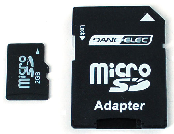
SD cards come in two popular flavors – microSD and SD. The interface, code, structure, etc is all the same. The only differences is the size. MicroSD are much much smaller in physical size.
Third, SD cards are ‘raw’ storage. They’re just sectors in a flash chip, there’s no structure that you have to use. That means you could format an SD card to be a Linux filesystem, a FAT (DOS) filesystem or a Mac filesystem. You could also not have any filesystem at all! However, 99% of computers, cameras, MP3 players, GPS loggers, etc require FAT16 or FAT32 for the filesystem. The tradeoff here is that for smaller microcontrollers (like the Arduino) the addition of the complex file format handling can take a lot of flash storage and RAM.
Formatting notes
If you bought an SD card, chances are it’s already pre-formatted with a FAT filesystem. However you may have problems with how the factory formats the card, or if it’s an old card it needs to be reformatted. The Arduino SD library we use supports both FAT16 and FAT32 filesystems. If you have a very small SD card, say 8-32 Megabytes you might find it is formatted FAT12 which isn’t supported. You’ll have to reformat these card. Either way, it’s always good idea to format the card before using, even if it’s new! Note that formatting will erase the card so save anything you want first.
Wiring

In this tutorial we will be using an Arduino to demonstrate the wiring and interfacing. If you have another microcontroller, you’ll need to adapt the wiring and code to match!
Because SD cards require a lot of data transfer, they will give the best performance when connected up to the hardware SPI pins on a microcontroller. The hardware SPI pins are much faster than ‘bit-banging’ the interface code using another set of pins. For ‘classic’ Arduinos such as the Duemilanove/Diecimila/Uno those pins are digital 13 (SCK), 12 (MISO) and 11 (MOSI). You will also need a fourth pin for the ‘chip/slave select’ (SS) line. Traditionally this is pin 10 but you can actually use any pin you like. If you have a Mega, the pins are different! You’ll want to use digital 50 (MISO), 51 (MOSI), 52 (SCK), and for the CS line, the most common pin is 53 (SS). Again, you can change the SS (pin 10 or 53) later but for now, stick with those pins.
- Connect the 5V pin to the 5V pin on the Arduino
- Connect the GND pin to the GND pin on the Arduino
- Connect SCK to pin 13 or 52
- Connect MISO to pin 12 or 50
- Connect MOSI to pin 11 or 51
- Connect CS to pin 10 or 53
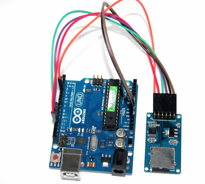
 That’s it! Refer to connecting picture below using bread board. Now you’re ready to rock!
Arduino Library & First Test
Interfacing with an SD card is a bunch of work, but luckily there is very nice Arduino library just for this purpose and it’s now part of the Arduino IDE known as SD (pretty good name, right?) You can see it in the Examples submenu.
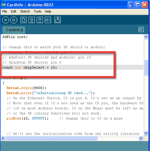
Next, select the CardInfo example sketch.

This sketch will not write any data to the card, just tell you if it managed to recognize it, and some information about it. This can be very useful when trying to figure out whether an SD card is supported. Before trying out a new card, please try out this sketch!
Go to the beginning of the sketch and make sure that the chipSelect line is correct, for this wiring we’re using digital pin 10 so change it to 10!
OK, now insert the SD card into the breakout board and upload the sketch.
Open up the Serial Monitor and type in a character into the text box (& hit send) when prompted. You’ll probably get something like the following:

It’s mostly gibberish, but it’s useful to see the Volume type is FAT16 part as well as the size of the card (about 2 GB which is what it should be) etc.
If you have a bad card, which seems to happen more with ripoff version of good brands, you might see:

The card mostly responded, but the data is all bad. Note that the Product ID is “N/A” and there is no Manufacturer ID or OEM ID. This card returned some SD errors. It’s basically a bad scene ! If you get something like this (where there is a response but it’s corrupted) you can try to reformat it or if it still flakes out, should toss the card.
Finally, try taking out the SD card and running the sketch again, you’ll get the following:
 It couldn’t even initialize the SD card. This can also happen if there’s a soldering or wiring error or if the card is really damaged.
Examples
- Card Info: Get info about your SD card.
- Datalogger: Log data from three analog sensors to an SD card.
- Dump File: Read a file from the SD card.
- Files: Create and destroy an SD card file.
- List Files: Print out the files in a diretory on a SD card.
- Read Write: Read and write data to and from an SD card.