How To Control a Stepper Motor with A4988 Driver with Arduino ?
In this tutorial we will learn how to control a Stepper Motor using the A4988 Stepper Driver Board.
Parts needed for this tutorial
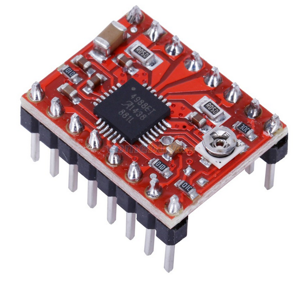
- A4988 Driver Breakout Board
- Arduino Uno Board
- Capacitor : 47uF
- Breadboard
- Jump wires
The A4988 is a microstepping driver for controlling bipolar stepper motors which has built-in translator for easy operation. This means that we can control the stepper motor with just 2 pins from our controller, or one for controlling the rotation direction and the other for controlling the steps.
The Driver provides five different step resolutions: full-step, haft-step, quarter-step, eight-step and sixteenth-step. Also, it has a potentiometer for adjusting the current output, over-temperature thermal shutdown and crossover-current protection. Its logic voltage is from 3V to 5.5V and the maximum current per phase is 2A if good addition cooling is provided or 1A continuous current per phase without heat sink or cooling.
 A4988 Limiting Specification
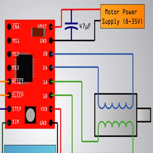
Now let’s close look at the pinout of the driver and hook it up with the stepper motor and the controller. So we will start with the 2 pins on the bottom right side for powering the driver, the VDD and Ground pins that we need to connect them to a power supply of 3V to 5.5V and in our case that will be our controller, the Arduino Board which will provide 5V. The following 4 pins are for connecting the motor. The 1A and 1B pins will be connected to one coil of the motor and the 2A and 2B pins to the other coil of the motor. For powering the motor we use the next 2 pins, Ground and VMOT that we need to connect them to Power Supply from 8V to 35V and also we need to use decoupling capacitor with at least 47µF for protecting the driver board from voltage spikes.

The next two 2 pins, Step and Direction are the pins that we actually use for controlling the motor movements. The Direction pin controls the rotation direction of the motor and we need to connect it to one of the digital pins on our microcontroller, or in our case connect it to the pin number 4 of Arduino Board. With the Step pin we control the mirosteps of the motor and with each pulse sent to this pin the motor moves one step. So that means that we don’t need any complex programming, phase sequence tables, frequency control lines and so on, because the built-in translator of the A4988 Driver takes care of everything. Here we also need to mention that these 2 pins are not pulled to any voltage internally, so we should not leave them floating in our program.
Next is the SLEEP Pin and a logic low puts the board in sleep mode for minimizing power consumption when the motor is not in use.
Next, the RESET pin sets the translator to a predefined Home state. This Home state or Home Microstep Position can be seen from these Figures from the A4988 Datasheet. So these are the initial positions from where the motor starts and they are different depending on the microstep resolution. If the input state to this pin is a logic low all the STEP inputs will be ignored. The Reset pin is a floating pin so if we don’t have intention of controlling it with in our program we need to connect it to the SLEEP pin in order to bring it high and enable the board.

The next 3 pins (MS1, MS2 and MS3) are for selecting one of the five step resolutions according to the above truth table. These pins have internal pull-down resistors so if we leave them disconnected, the board will operate in full step mode. The last one, the ENABLE pin is used for turning on or off the FET outputs. So a logic high will keep the outputs disabled.
Circuit Schematics
Here’s the complete circuit schematics. We will use the drive in Full Step Mode so we will leave the 3 MS pins disconnected and just connect the Direction and the Step pins of the drive to the pins number 3 and 4 on the Arduino Board and as well the Ground and the 5V pins for powering the board. Also we will use a 100µF capacitor for decoupling and 12V, 1.5A adapter for powering the motor. We will use a NEMA17 bipolar Stepper Motor and its wires A and C will be connected to the pins 1A and 1B and the B and D wires to the 2A and 2B pins.

Current Limiting
Before we connect the motor we should adjust the current limiting of the driver so that we are sure that the current is within the current limits of the motor. We can do that by adjusting the reference voltage using the potentiometer on the board and considering this equation: Current Limit = VRef x 2.
 However this equation is not always correct as there are different manufactures of the A4988 driver board. Here’s a demonstration of our case: We adjusted the potentiometer and measured 0.6V reference voltage. So the current limiting should be that value of 0.6*2, equal 1.2 A.
 Now because we are using the Driver in Full Step Mode and according to the A4988 Datasheet in this mode the winding current could reach only 70% of the current limit, the 1.2A*0.7 would equal 0.84A. In order to check this we uploaded a simple code that sends continuous logic high to the Step pin (so that we can better notice the current) and connected meter in series with one winding of the motor and powered it up. What we got was 0.5A which means that the equation wasn’t correct for our case.

Source Code
Here’s an example code. First we have to define the Step and Direction pins. In our case they are the pins number 3 and 4 on the Arduino Board and they are named stepPin and dirPin and the setup section we have to define them as an outputs.
/*     Simple Stepper Motor Control Exaple Code
 *
 *
 */

// defines pins numbers
const int stepPin = 3;
const int dirPin = 4;

void setup() {
  // Sets the two pins as Outputs
  pinMode(stepPin,OUTPUT);
  pinMode(dirPin,OUTPUT);
}
void loop() {
  digitalWrite(dirPin,HIGH); // Enables the motor to move in a particular direction
  // Makes 200 pulses for making one full cycle rotation
  for(int x = 0; x < 200; x++) {
    digitalWrite(stepPin,HIGH);
    delayMicroseconds(500);
    digitalWrite(stepPin,LOW);
    delayMicroseconds(500);
  }
  delay(1000); // One second delay

  digitalWrite(dirPin,LOW); //Changes the rotations direction
  // Makes 400 pulses for making two full cycle rotation
  for(int x = 0; x < 400; x++) {
    digitalWrite(stepPin,HIGH);
    delayMicroseconds(500);
    digitalWrite(stepPin,LOW);
    delayMicroseconds(500);
  }
  delay(1000);
}
In the loop section first we will set the Direction pin on high state that will enable the motor to move in a particular direction. Now using this for loop we will make the motor make one full cycle rotation. As the driver is set on Full Step Mode and our Stepper Motor has 1.8 degrees step angle, or 200 steps, we need to send 200 pulses into the Step Pin to make one full cycle rotation. So the for loop will have 200 iterations and each time it will set the Step pin on high and then low state for making the pulses. Between each digitalWrite we need add some delay from which the speed of the motor will depend.
After this full cycle rotation we will make one second delay, then change the direction of rotation by setting the dirPin on a low state and now make 2 full cycle rotations with this loop of 400 iterations. At the end there is one more second delay. Now let’s upload the code and see how it will work.
We made one more example for this tutorial, where we control the speed of the motor using a potentiometer. Here’s the source code of that example:
/*     Simple Stepper Motor Control Exaple Code
 *
 *
 */

// Defines pins numbers
const int stepPin = 3;
const int dirPin = 4;

int customDelay,customDelayMapped; // Defines variables

void setup() {
  // Sets the two pins as Outputs
  pinMode(stepPin,OUTPUT);
  pinMode(dirPin,OUTPUT);

  digitalWrite(dirPin,HIGH); //Enables the motor to move in a particular direction
}
void loop() {

  customDelayMapped = speedUp(); // Gets custom delay values from the custom speedUp function
  // Makes pules with custom delay, depending on the Potentiometer, from which the speed of the motor depends
  digitalWrite(stepPin, HIGH);
  delayMicroseconds(customDelayMapped);
  digitalWrite(stepPin, LOW);
  delayMicroseconds(customDelayMapped);
}
// Function for reading the Potentiometer
int speedUp() {
  int customDelay = analogRead(A0); // Reads the potentiometer
  int newCustom = map(customDelay, 0, 1023, 300,4000); // Convrests the read values of the potentiometer from 0 to 1023 into desireded delay values (300 to 4000)
  return newCustom;
}