Controls a maximum of 6 PWM fans !
In a modern PC you will find a number of fans for removing the heat that is generated. These can’t always be controlled individually by the PC motherboard. With the help of the circuit described here you can actively control up to six fans, while the temperature can be measured in various places inside the PC case using a number of sensors. A PC program is used to configure and monitor the fans, which communicates with the fan control board via a USB link.
A number of years ago Intel created a specification for 4-wire PWM driven PC fans, see [1]. These fans are hardly more expensive than the well-known 2-pin and 3-pin varieties, although they have the advantage that their rotational speed can be controlled using a PWM signal. The 3-pin and 4-pin connectors also include a tachometer signal that can be used to feed the instantaneous speed of the fan back to the motherboard. A PC motherboard often has only a single fan connector that includes a PWM signal, although a PC usually contains several fans. There is no choice but to run these other fans at a fixed speed. And even if there is a facility to connect several PWM fans, it usually isn’t possible to control them individually from the motherboard.
The circuit described here is capable of controlling the speed of up to six fans in a PC in a safe and flexible manner, so that they will run at their minimum required speed and hence keep the noise level as low as possible.
 Figure 1. The circuit consists mainly of an Atmega microcontroller and a large number of connectors.
The circuit
It can be seen from the circuit diagram in Figure 1 that the circuit itself is very straightforward. It consists of not much more than an Atmega microcontroller and a number of connectors for connecting the fans, sensors, USB and power supply. The 4-wire fans are connected directly to the microcontroller, since they are able to cope with the generated PWM signals without any further processing. The internal pull-ups of the microcontroller make sure that the open-collector tachometer signals from the fans are pulled towards the positive supply voltage. R3/C2 is a low-pass filter that smooths (integrates) the incoming PWM signal from the motherboard, so that an analogue input of the microcontroller can be used to read the PWM control signal from the motherboard. For the analogue temperature sensors you can use two 10 kΩ NTC sensors, which are connected to K11 and K12. Together with the NTCs, R8 and R9 form two potential dividers that are connected to ADC2 and ADC3 of the microcontroller. If you wish, you can connect a maximum of eight I2C temperature sensors to K10. R6 and R7 are the required pull-ups on the bus. The firmware has been tested with Microchip MCP980x sensors, but similar sensors such as the TCN75 should work either directly or with a small modification. When the firmware starts it figures out itself how many sensors are connected to the I2C bus. Jumper J1 is used to select either the USB bus or the PC as the source of the power supply for the microcontroller. During firmware development, when no fans are connected, it can be convenient to power the circuit via the USB bus, but normally the PC supply would be used (jumper on pins 2 and 3).
Construction
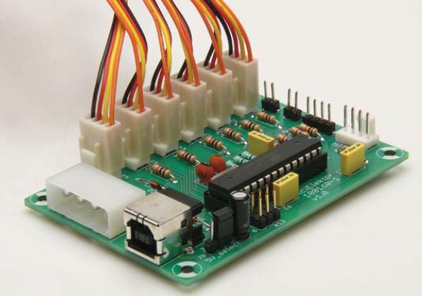
Since the circuit doesn’t have any SMDs the construction is quite easy, especially if you use the PCB designed for this project (Figure 2). The large connector (K8) is the male version of the well-known PC hard drive connector, made by Molex. If required, the power supply cable could also be soldered directly to the board. The official 4-pin fan headers (K1 to K7) may be difficult to get hold of in small quantities. The 3-pin version, however, is much more widely available. The form and connections of both connectors are identical, so that 3-wire fans can be connected to 4-pin headers. Conversely, if you mount a 3-pin fan header and in the space for the fourth pin mount a single header pin you end up with the equivalent of a 4-pin header (see Figure 3). This makes it easy to connect PWM fans without the risk of connecting them the wrong way.
 Figure 2. With this PCB the construction of the circuit becomes child’s play!
Firmware
The software for the microcontroller is written in C and makes use of a software-based USB stack V-Usb (see [2]) to communicate with a PC. The software was initially developed for an ATmega88, but this was soon found to be too small to accommodate all the functions it was required to perform. For this reason we changed over to the ATmega168, which has double the amount of flash memory. However, it is still possible to compile the software for the ATmega88, although with a reduced functionality (refer to the file config.h in the download available from the Elektor website [3]). As mentioned in the Intel specification for 4-wire fans, they should be controlled with a PWM signal with a frequency of about 25 kHz, where the rotational speed should follow the duty cycle linearly from 20% upwards (at lower duty cycles the speed is undefined). The ATmega contains six PWM outputs, but only two of these (which are driven by the 16-bit Timer1) can be set to exactly 25 kHz. The other PWM outputs are driven by 8-bit timers and can be set to either 7.8 kHz or 62.5 kHz. A little trick is used to make them operate at the required frequency. They are set to operate at the lower frequency of 7.8 kHz, but then the overflow interrupt of Timer1 is used to restart the 8-bit timers, which causes all PWM outputs to operate at 25 kHz.
The pulses from the tachometers, which are used to measure the rotational speed of the fans, are counted using the pin-change interrupt. In practice the fans rarely went faster than 6000 revolutions per minute, where the tachometer outputs two pulses per revolution. When all fans run at full speed this means that the software has to deal with about 1200 pin-change interrupts per second. This may seem like a lot, but the main loop is quite simple which leaves plenty of time for calculating the duty cycles.
 Figure 3. With the addition of an extra pin you can use a 3-pin fan header to make up a 4-pin connector for a PWM controlled fan.
This main loop checks every second if any of the fans has stopped, for example because of a fault or obstruction. Depending on the settings, a stalled fan can cause the simulated tachometer signal to stop, thereby signalling to the motherboard that a fan has stopped. Any function on the motherboard that raises an alarm when a fan fails will therefore continue to work. Next, the current sensor values are read, all the calculations are carried out and the values for the duty-cycles are written into the output-compare registers for the timers. The interval of one second for calculating the new duty cycles may seem like quite a long time in the world of microcontrollers, but it is quite suitable for controlling a slow changing process such as the temperature inside a PC.
The simulated tachometer signal for the motherboard has to be able to provide a maximum of about 1200 pulses per second, where the timing doesn’t have to be that accurate. For this reason the pulses are generated from the main loop, where the tachometer pin is made to go alternately in a low state and a high-impedance state in order to reproduce the required open-collector output. With the help of the PC software the current configuration for the controller can be stored in the EEPROM, so that it can be automatically loaded when the circuit is turned on again. A large part of the software consists of the USB stack and the routines for exchanging messages with the PC. The ‘realtime’ communication with the PC is taken care of by the INT0 handler, which has the highest priority.
Software
The PC software has been written in C++ and was developed using the free Microsoft Visual C++ 2010 Express. The graphical interface makes use of wxWidgets, which means that it can be used both under Windows as well as Linux (and OS X too, but this has not been tested in practice by the author). LibUsb has been used to communicate with the circuit via a USB link. A separate library has been used for the creation and exchange of messages. This hides the details of the communication between the PC and the circuit and promotes the re-use of the routines. From here you can directly set the rotational speed of fans or read the sensor values. The graphical interface consists of the following tabs:
- Admin
Here you can manage the EEPROM, such as reading or writing the configuration. Remember to store a good configuration into the EEPROM at the first opportunity, otherwise the circuit will have a blank configuration when it restarts! - Sensor0 ~ Sensor7
The sensor tabs let you assign the connected sensors to a sensor input and inspect their value graphically over time. - Fan0 ~ Fan5
Here you can configure the individual fans. - Fan Out
This is used to configure the simulated tachometer signal to the motherboard.
Before a sensor can be used as a controller in the circuit it needs to be assigned to a sensor
input.
Figure 4 shows an example of the configuration for Fan0, which is connected to K1. At the top-left the type of fan (so the software knows if a tachometer and/or PWM signal can be used) and the type of control can be selected. In this example the I2C sensor with address 0 (Temp_I2C_Addr0) measures the temperature of the outside air that is sucked into the PC case and the sensor with address 7 (Temp_I2C_Addr7) measures the temperature inside the case itself. Since the PC generates heat itself, it would be unrealistic to expect to get the
inside temperature the same as the outside temperature. The controller will therefore be configured such that the inside temperature will be at most 2 °C higher than the outside temperature (the setting +2 after the set point). The PI (Proportional-Integral) control selected here continuously calculates the difference between the required temperature (outside temperature +2°C) and the measured inside temperature. The controller will increase the rotational speed of the fan proportionally (using factor Kp) and also take account of integrating errors over time (factor Ki). In the figure you can see that the fan starts of slowly at a duty-cycle of 0%. When the inside temperature increases (the dark blue
line) above the required temperature (the light blue line), the controller ensures that the rotational speed of the fan increases (the green line, in revolutions per second). When the required temperature has been reached again after some time the rotational speed gradually decreases.
 Figure 4. A screen dump of the associated PC program that is used for the configuration and monitoring of the fans.
Another possible application for this circuit is to synchronise the speed of several fans in order to keep vibrations in the PC case to a minimum. To do this, use a PI controller with the rotational speed of one fan as the sensor for all other fans and negative factors for Kp and Ki. On the final tab you can configure the source for the simulated tachometer signal to the motherboard, such as the fan with the lowest rotational speed or a copy of one of the connected fans. For each fan a minimum required rotational speed can be specified. If it falls below this limit the software considers that the fan has stalled and the simulated tachometer signal to the motherboard will be stopped.
Component List
| D1, D2 = 3.6V Zener diode | IC1 = ATmega168PA-PU | X1 = 16MHz Quartz Crystal | R1, R2 = 68Ω |
| R3 = 100KΩ | R4, R8, R9 = 10KΩ | R5 = 1.5KΩ | R6, R7 = 4.7KΩ |
| R10-R15 = 1KΩ | C1 = 10μF/16V Radial | C2, C5, C6 = 100nF | C3,C4 = 22pF |
Project Software
![]()