Programmable camera controller
 This project dubbed TimeClick controls a digital SLR camera without human intervention using a wired connection. It can take photographs at fixed or random time intervals or in response to sensor input, which makes it suitable for various purposes from HDR photography to sound-triggered pictures.
This project came about after having taken too many photos randomly at events like parties. This way of operating a camera can lead to funny results at best. However, as the project developed, the author started to have new ideas and added several new features to extend the functionality, such as:
- Fixed delay between photos
- Random delay between photos
- Sensor input to trigger photos
- Manual operation for use as wired remote
- Bulb mode
- Mirror lock
- Exposure bracketing
- 12 presets to save different sets of configurations
Operation is remarkably simple and once the device is confi gured and wired to the camera, you simply choose the right spot for the camera on a tripod and let it do all the work. Depending on the power source used for the device and the camera, you can have the camera in operation for days.
Tools used
The circuit started out on a breadboard and later evolved into a complete PCB design. For the hardware design (schematics and PCB) open-source CAD program Kicad was used. It is very easy to use, even for first time users. Since the author has done everything at home (PCB making using the ironing method), no metallised holes have been used and all connections between both layers of the PCB are made using wires or component pins.
For the software design AVR Studio 4 was the development tool. The microcontroller programming was done with Atmel’s AVR Dragon using ISP mode. In the beginning the author experienced some troubles with AVR Studio and AVR Dragon. Sometimes AVR Studio seemed to be able to connect to the AVR Dragon but unable to communicate with the microcontroller. This problem was solved once by restarting the computer and ultimately by completely reinstalling AVR Studio. From what can be found in postings on the Internet by users with similar problems, we’ve a hunch it was caused by a bug in AVR Studio mixed with inappropriate procedures.
The advised procedure for programming the microcontroller can be found under Assembling & Programming.
Hardware Description
Starting with the power supply, there are two options for powering the device. One is using an internal 9-V battery, the other is using an external power supply. A power switch has been added in this section of the circuit, see Figure 1. The author’s prototype used six AAA batteries instead of a 9-V block battery, mostly because of the poor battery life of the 9-V block type (IEC 6LR22). Under normal operation the circuit consumes about 10mA with the LCD backlight off. If the LCD backlight is on, current consumption rises to about 100mA. To save energy during operation, the LCD backlight is turned off automatically when no buttons are pressed for 10 seconds. To turn the backlight on again, just press any of the device’s buttons.
Figure 1. Schematics
Since the LCD needed 5V and the same voltage was suitable for powering the rest of the circuit, the author went for a standard voltage regulator. Thus, the first pick was the well known 7805. However, a quick change of mind occurred after a close look at the datasheet. A 7805 needs at least 7 volts at its input to be able to stabilise its output at 5V. This of course isn’t any good when you want to power your circuit from batteries. Moreover, the 7805 is not known for its high efficiency…
As result of all this, an LP2954 seemed much more appropriate. This is a regulator with reverse battery protection and a low dropout voltage which helps to extend battery life.
There is a battery level indication option included using R11, R12 and a free ADC port (ADC9) of the microcontroller. The heart of this circuit is an ATMELATtiny861 which fits the bill exactly. The main reason for the author to choose this microcontroller instead of another from the Atmel family was mostly because of its availability in SOIC-20 package. This package is not too hard to solder and still is relatively small. The microcontroller operates at 1 MHz. Here, you have two options: just use a crystal of 1MHz or an 8MHz device and set the CKDIV8 fuse when programming. The 2×16 LCD is used to show information and allow the user to configure the device. It’s being used in 4-bit mode and the LED backlight is controlled by the microcontroller through N-channel FET T2.
The keyboard input is implemented using one ADC input (ADC6) instead of several (digital) ports. That way there is no need for a controller with more input ports and consequently no larger package is needed. The voltage the ADC reads depends on the key pressed. When no key is pressed, the ADC will read roughly 5V. All ADCs work in 10bit mode, which means the value read lies between 0 and 1023. With 5V on the ADC pin, the software will read 1023. If a key is pressed, the voltage on the ADC pin may be calculated using the formula:
VADC = VCC – (R15 × VCC) / (R15 + RSW)
where VCC = 5 V, R15 = 10 kΩ and RSW = 1.5 kΩ, 5.6 kΩ, 15 kΩ or 68 kΩ depending on the switch pressed. The four keyboard switches have the following functions: MENU, MINUS, PLUS and ENTER, with which you can adjust the setting of the TimeClick.
ADC5 is used for sensor input. The sensor is connected through a 3.5-mm jack socket. At the tip there is 5V available for powering the sensor. The ring carries the sensor output signal and the shield is grounded. There are three types of sensor included in the schematic: a light sensor, a sound sensor and a vibration sensor (piezo). But of course the sensor range can be extended to whatever sensor you need. To avoid connection mistakes, the sensor input jack and the output jack have different sizes. The output signal is available at a 2.5-mm jack socket, as found on some Canon cameras. For safety reasons the output of the microcontroller is coupled to the jack via an optocoupler. This device can be used with many different camera models (see inset Camera Compatibilty Guide); you only need to have the right adapter cable and the camera should be able to work with the implemented protocol.
This protocol is rudimentary: it uses three pins: 1—ground; 2—ring and 3—tip. When pins 1 and 2 are shorted, the camera behaves the same as when the shutter button is half way pressed. When pins 1 and 3 are shorted, the camera behaves like the shutter button is fully pressed.
Sensor operation
The way the sensors work is very easy to understand. The microcontroller reads the ADC input receiving the voltage a sensor generates. Regardless of the type of sensor used the microcontroller waits for a transition (rise or fall) across a trigger value. When this condition is met, it acts accordingly depending on the configuration, i.e. waits a configured time expressed in ms and then fires the shutter. Always turn off the power before plugging and unplugging the sensors. This way short circuits inside the mini-jack connectors are avoided.
Software description
The source code, was written completely in C language using the very efficient compiler avr-gcc. About 99% of the 8K flash space of the microcontroller is used to store the program. It was hard to squeeze all the features into the device. Several code optimisations were required. All configuration data are preserved in the EEPROM of the microcontroller.
The program operation is clearly commented; the program does the initial setup and then enters an endless loop. Inside this loop is where all the action happens. TIMER0 is configured to generate a pulse every second to take care of all timing multiples of 1 second. To allow for maximum flexibility, there are 12 different profiles where the user can save different operating configurations. Each profile can be renamed to indicate the function it was created for. For example, the user can have a profile for ‘Lightning’, one for ‘Drops’, and so on. Included in the source code is a file with the EEPROM contents of several preconfigured modes.
 Figure 2. Component layout
Assembling & Programming
When assembling your device, start with the lowest profile components and work your way up to the tallest ones. Figure 2 shows the PC board component layout. The LCD and switches need to be mounted on the copper side of the PCB. Once the board is populated, it is time to put some intelligence in! The programming of the Atmel microcontroller is done by way of ISP connector K1. Assuming you’re using AVR Studio and AVR Dragon / AVR ISP programmer, here is what you should do:
First choose the appropriate device in the menu Project -> Configuration options.
Next, the programmer and the TimeClick device should be connected. However, since the author experienced some mysterious occurrences in this step, he advises to stick to the following order:
- With both TimeClick and AVR Dragon/ISP powered OFF, connect the ISP cable between them.
- Then connect the AVR Dragon/ISP to aUSB port capable of supplying more than 300mA.
- Now you can power up TimeClick.
Next, go to the menu Tools -> Program AVR-> Connect to choose the appropriate programmer/port and press Connect. Figure 3 shows the window you should see right now. It’s important that the programming mode is set to ISP and that the ISP frequency is set to 125KHz (< ¼th of the device clock). If everything checks out, an ‘OK’ should be returned after you press Read Signature.
 Figure 3. Connecting to the device.
Now we’re ready to set the fuses to the correct values as shown in Figure 4. SPIEN is active as factory default. If you used an 8MHz crystal, you should also check the CKDIV8 fuse as shown in the screen capture. It is also important to set the correct clock source, in this case select ‘External Crystal 3.0-8.0MHZ’. The Brown-out detection could avoid EEPROM corruption with batteries at the end of life, so set this to 4.3 V.
 Figure 4. Setting the fuses correctly.
Finally, it’s time to program the device. All the needed files are inside the ZIP-file associated with this article. Download and extract this file. In the flash area, select the file TimeClick.hex and hit the Program button (Figure 5). At the end, the device will reboot.
 Figure 5. Programming the microcontroller.
If you want to use the preconfigured EEPROM settings, in the EEPROM area select the file TimeClick_Configured_eeprom.hex and hit the Program button.
Software Operation
With the device programmed, it’s ready for use. When the ENTER key is pressed and held during device power on, a reset to factory defaults of all configuration possibilities can be carried out. This option will erase all saved configurations, even the preconfigured EEPROM settings mentioned before. In the main screen the following information is always visible:
- Battery level in steps of 25%
- Sensor mode
- Operation mode
- Active profile
- Number of photos taken so far
- Metering setting
- Bulb setting
- Mirror lock setting
- Exposure bracketing setting
Some of this information is presented using custom characters defined in the software. Pressing the MENU key while the main screen is being displayed, enables the user to enter the menu where the configuration takes place. The menu is intuitive and easy to navigate. Press MENU to go back, PLUS and MINUS to change values and ENTER to go forward.
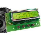
 Figure 6. Information shown on display.